The Air Unit is similar to the ESP32 board from Sumobots, however with additional systems on board to support flight. Some of the features of the Air Unit include:
- LiDAR, for millimetre altitude control (VL53L1- same type used on the latest Dyson robots)
- IMU, for rotation sensing to stabilize flight (ICM42688- highest accuracy consumer MEMS gyro on the market)
- Barometer, for backup/high altitude control (580- latest from Bosch)
- Switching regulator, to allow direct supply from lithium batteries and operation down to 3V
- 8 GPIO pins broken out- these use an FPC cable to connect to expansion boards
- USB-C, because at UBRobotics we live large
- 4x RGB LEDs, allowing for your drone to do a very convincing Christmas tree impression. Last year people expressed concerns with how bright the LED was, so this year I quadrupled the number of them. Enjoy.
Through this tutorial, make sure to use the code glossary included on the github- it has the syntax for various commands. You'll also find the arduino code here, which you'll need to modify through the workshop.
The Air Unit uses an ESP32-S3, which is a major upgrade from the base ESP32 (although unlike last year, you guys used the S3 in Sumobots). One of the benefits is direct connection to USB, without a programming chip.
However, you’ll need to bootstrap it the first time. You can do this simply by holding down the BOOT button as you plug it in, to put it into boot mode. In this mode, it won’t run any code- it’ll just wait for a download.
Now you should see a port available for download and can proceed as normal. Under “Tools”, make sure to enable “USB CDC on boot” to ensure it will print to the terminal.
Hit upload with a blank sketch to save these settings to the ESP32-S3. If in later steps you can’t get the board to print text, make sure these settings are correct.
From here, you can make a new sketch and write a simple “Hello World” program to check that the ESP32-S3 is working:

If successful, the unit will print Hello World very quickly into the serial monitor- the system is working.
However, if you attempt to upload a new sketch you will probably see something like this:
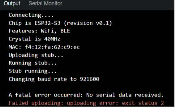
This is because the USB connection is overloaded. This is a possible issue with the ESP32-S3 onboard USB, but it can be fixed by using the BOOT button.
Add a 1000ms delay into the sketch after the print statement, and then unplug the ESP32-S3. Hold down the button marked BOOT, plug in the USB cable and then release the BOOT button. You should be able to see this message in the serial terminal:

Uploading should now be successful, and the program will run after you reboot the ESP32-S3- this time printing the text once per second. From here, you can upload the code without using the BOOT button. If there are issues with uploading to the ESP32-S3, try the BOOT button to recover it.
When working with UAVs, the main loop will run thousands of times per second, which means a print statement in the main loop can cause the ESP32-S3 to lock up.
You can also tap the reset button instead of unplugging the Air Unit.
Use neopixelWrite() to set the colour of the LED, which is connected to pin 48. If you call this command repeatedly, it will control each subsequent LED.
You can use (brightness+brightness*sin(i)/2) to have the brightness of each channel fade smoothly between zero and brightness.
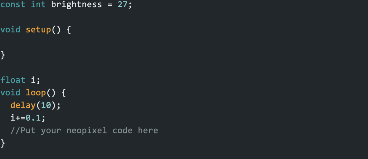
To test how long this command takes, create a variable called:

Set startTime to micros() before the code to be measured, and endTime to micros() once it has run. You can then read out the difference between the two out on the serial monitor. How long does this command take?
Last off, let’s take advantage of all 4 (4x as many as last year) RGB LEDs. This might seem crazy, but you’ll love it. Copy paste the LED command so it gets called 4 (4x as many as last year) times, and they should all light up. It’s… so beautiful… (4x as beautiful as last year)
For dynamic systems, it’s important to make sure that your code can run fast enough to react to changes in the environment. The ESP32 has two cores, so you can put code like this which isn’t time critical on one, and the more important code on the other. However, using more direct control over the peripherals we can offload this work from the CPU to a transmittion controller- you’ll be able to see how this works later on.
For an extension, use right click the LED command and select “peek definition” to see the code that runs underneath it. Can you modify it to send 4x as much data? What about making it non-blocking?
Hint:
Smart LEDS accept a packet of 24 bits (8x each colour), and then forward all subsequent bits- so sending 96 bits will light all LEDs. The RMT buffer here is too small for this, but can be easily adjusted.
The Digital Information Superhighway
Engineers working with digital systems report 24% higher job satisfaction and have a 16% more positive outlook than analog engineers (Source: personal experience). UBRobotics exists to make you happy, so let’s digitize.
All of the sensors on this drone are too accurate to convey this data over analog signals- the Analog to Digital Converters have a resolution of 4096, and the IMU has a resolution of 65536. Even with better analog resolution, the wires would pick up too much noise to get near this. We’ll show you three levels of implementation here: running an example sketch from a library, using an API to talk to a sensor and finally direct control of the device from first principles using a “register map”- more on that later.
Libraries are the easiest way to talk to a sensor, with everything you need to get it working. However, they often are slower than a more direct approach- for example, perhaps they’ll read 6 values from the sensor when we only need 1. They can also be bloated, with many features and protections which aren’t needed in a given application.
IMPORTANT! WE NEED TO MODIFY THE SKETCH TO WORK ON OUR CUSTOM BOARD BEFORE YOU UPLOAD IT
To install one, click on the highlighted book icon
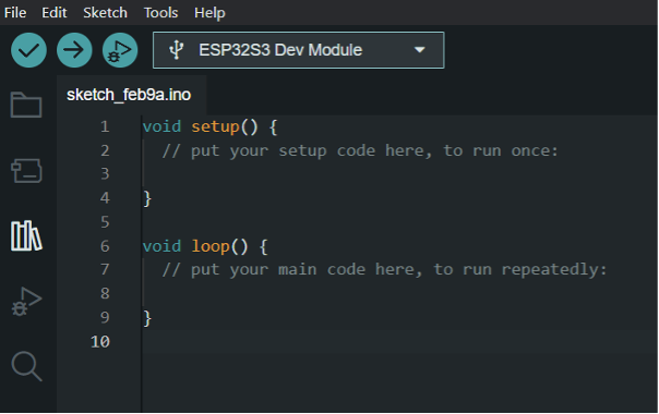
From here, search for BMP581 (That’s not a typo, the BMP580 isn’t generally for sale but I know a guy. The BMP581 library works for it though).
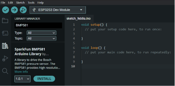
Install the Sparkfun library.
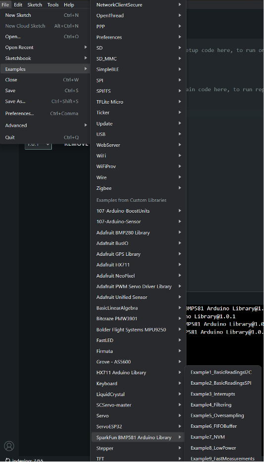
Navigate through these menus, to Example 1: Basic Readings I2C
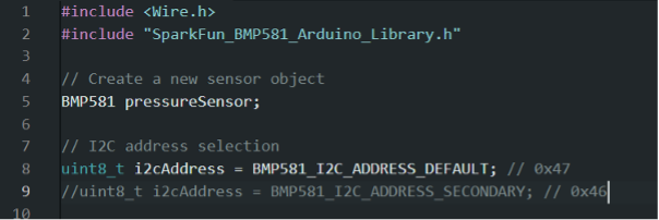
Comment out line 8, and uncomment line 9

Change line 18 to Wire.begin(36,35);
It should start printing out temperature and pressure, once a second. You can adjust the delay at the end of the sketch (line 58) to 50 to speed up the measurements, and delete all print statements except Serial.println(data.pressure) so that only the pressure is sent allowing it to be shown on the data plotter. Move the board up and down, line moves up and down (but in reverse, thinner air higher up). You’ll also probably see a fair amount of noise and drift- especially if you’re in a room with an open door/window. Next week, we’ll look at a way to fix this- but for the time being, let’s look into a more precise sensor
Using the LiDAR
The board has a VL53L1 LiDAR, with up to 8 meters of range in “ideal” conditions (yea, and I’m 6’5 if you measure me in “ideal” conditions). This will allow for your drone to maintain a steady height above the ground, making learning to fly much easier.
For this one, I have ported the STMicroelectronics driver to be compatible with ESP32. Instead of using a library with example programs, like with the BMP580, you’ll be working with an API- this is the layer below, where you’ll handle direct functions of the LiDAR but not have to worry about exact digital commands (more on this in the final section).
For this step, use the VL53_DRIVER_Y2 sketch. There should be helpful comments on all the lines you need to change though out this process.
A useful feature on the Arduino IDE 2.0 is code folding- hover to the left of a function and an arrow should appear. Click this to minimize the function to one line, making it easier to quickly read over the code. You can use this to collapse all of the API functions, so that you can quickly read them in the next section and find which function corresponds to each step. Setup and loop are right at the bottom of the code,
In setup, add a line of code to the while loop to set the booted variable to the boot state of the VL53. Then, call the initLiDAR function to flash the default settings to the VL53.
In the main loop, make the while loop check if data is ready. next use the corresponding functions to set range and status. Range will be the distance in mm, and status will return 0 if the data is good.
Once you’ve done that, clear the interrupt to have the VL53 start another read.
One last thing- there should be a little plastic cover over your LiDAR. The optics are somewhat fragile, and this is there to protect them. However, to get accurate readings you’ll need to permanently remove this by peeling it off with the small tab below the optics. I’ve found it mostly works with this thing on, but it will struggle more in bad lighting or at high altitudes.
Deeper Details
There are two digital interfaces to the sensors on the air unit: SPI and I2C.
SPI
The Serial Peripheral Interface uses four lines:
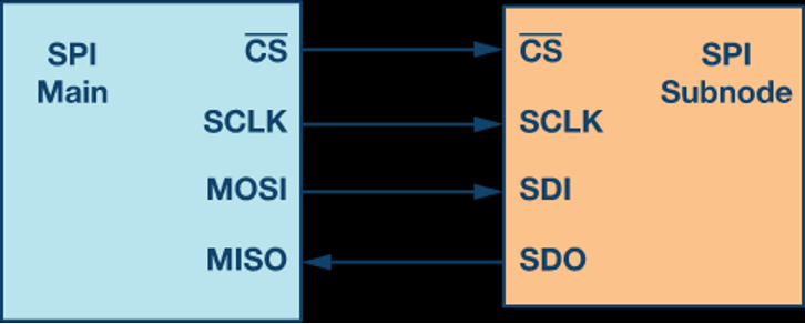
Credit: Analog Devices
- The CS line allows for a device to be selected without an address being broadcast, which saves time
- MOSI is data travelling out from the ESP32-S3
- MISO is data travelling out from the IMU
- SCLK is the clock signal, which allows for data to be read on the MOSI/MISO lines at the right time
The IMU can run SPI at 24,000,000 bits per second- that’s fast.
If you want to learn more about SPI, have a look at this:
https://learn.sparkfun.com/tutorials/serial-peripheral-interface-spi/programming-for-spi
I2C
Four wires? For one sensor? And another wire for each additional sensor? That’s a lot. It’s worth it for the IMU, which we’ll read thousands of times per second, but for the rest of the sensors it’s overkill.
I2C is good for large numbers of slower sensors, needing only 2 wires for over 100 sensors. Each device has an address, which removes the need for a chip select line, and data can move in both directions on the data line combining SDI and SDO into one line. On the ESP32S3 I2C can only run at 400,000 bits per second- pretty grim compared to SPI, but if we don’t have too much data to move then it won’t matter.
Where's the Data at?
Digital sensors use a register map: think of this like a table, or a spreadsheet:
|
Register Number |
Data |
|
0 |
15 |
|
1 |
19 |
|
2 |
255 |
|
3 |
0 |
To read this data, we can send a register address to the device and it will send the data back. We’ll need to tell the device that we’re reading though- we can do this by adding 128 to the register address (or 0x80 in hexadecimal).
For example, if we call SPI.write(1+0x80), the device will write back 19- which we can then read with SPI.read().
Sometimes, we can write the data- to do this, we’ll simply send the resister address and then the new value. For example, SPI.write(1) followed by SPI.write(200) will change the table to be like so:
|
Register Number |
Data |
|
0 |
15 |
|
1 |
200 |
|
2 |
255 |
|
3 |
0 |
That’s nice, but what do these numbers mean?
Using a Register Map
Most devices come with a register map, which tells us what the data means:
|
Register Number |
Read/Write |
Description |
Data |
|
0 |
Read Only |
Device ID |
DEVICE_ID[7:0] |
|
1 |
Read/Write |
Measurement mode |
MODE[7:0] |
|
2 |
Read Only |
Measurement data high byte |
MEASUREMENT_H [7:0] |
|
3 |
Read Only |
Measurement data low byte |
MEASUREMENT_L[7:0] |
This is an example of a register map, where some values are fixed, some are read only and others can be set by the user. We’ll try a practical example on the drone’s IMU.
The IMU
The Inertial Measurement Unit (IMU) on this board uses Serial Peripheral Interface (SPI) to communicate. The code that makes the IMU work is mostly in the attached files, not the main sketch- you can change between files here:

With most of the code being in ICM42688RB.cpp.
Registers
Most serial devices use what is known as a register map. The register map for the ICM42688 can be found here, at page 61:
https://invensense.tdk.com/download-pdf/icm-42688-p-datasheet/
This section will use the UsingTheICM1 code.
The best way to check than a device is working is to read the ID of the device- this is a register that will always hold a value that you can find in the datasheet- in this case, the value of the WHO_AMI_I register is always 71. Open the UsingTheICM1 sketch. Run the code, and it should report that the IMU can’t be found. Then reason for this is that the readIMURegister function doesn’t do anything and always returns 0. I’ll tell you which functions to use, but you’ll need to figure out what values or variables to pass to them- feel free to use the code glossary for this.
For SPI, a transaction has 4 steps:
Turn the Not Chip Select (NCS) pin, which is pin 18 here, low using digitalWrite().
Send the register address (which will be “reg”), with the first bit set to 1, to the IMU using SPI.transfer().
Send 0x00 to the IMU- at the same time you send this, the IMU will send back the data we need. Set the variable regData to this, so the function will return it.
Turn the NCS pin high again.
Hint: Setting bits
To “set” a bit, we’ll use a bitwise “or” operation: “reg | 0x80”. This will force the first bit of the register address to be 1.
|
|
R/W |
Address |
||||||
|
Register Address (117) |
0 |
1 |
1 |
1 |
0 |
1 |
0 |
1 |
|
Write flag (0x80) |
1 |
0 |
0 |
0 |
0 |
0 |
0 |
0 |
|
Value to be sent to the IMU (245) |
1 |
1 |
1 |
1 |
0 |
1 |
0 |
1 |
This section will use the UsingTheICM2 code.
All’s good and well reading the ID of the device, but you can find that on Google pretty easily. What can’t be Googled is the IMU data- acceleration and rotation speed of your drone.
To do this, we’ll need to do a bit more work- by default, the IMU is turned off, so we’ll need to turn it on. I’ve added commands to do this for you, but the #define statements are lacking register numbers except for WHO_AM_I. Use the register map to find what number the missing register numbers are. I’ve also moved all the SPI functions to a second file, just to make the code less cluttered.
Remember, if a number is in hexadecimal use “0x” before it in the code- the register map has hexadecimal in the first column, and denary in the second.
This section will use the UsingTheICM3 code.
In the previous step you’ll notice that the data changes when you move the board, but it’s probably almost impossible to interpret any meaning from it. This is because the data for each axis is two bytes long, but we can only move one byte at a time. Here’s what that looks like:
|
int16_t |
|||||||||||||||
|
High Byte |
Low Byte |
||||||||||||||
|
-32768 |
16384 |
8192 |
4096 |
2048 |
1024 |
512 |
256 |
128 |
64 |
32 |
16 |
8 |
4 |
2 |
1 |
|
1 |
0 |
0 |
1 |
1 |
0 |
1 |
0 |
1 |
1 |
1 |
0 |
1 |
0 |
1 |
1 |
Notice that the leftmost bit represents a negative number? This is how we can communicate positive and negative values, although it does mean the raw data is hard to read. To get this data into a more usable form, we’ll need to merge the bytes into an int16_t- a 16-bit long number that can be positive or negative.
Combine these two operators to fuse the first two bytes in data[] into a single 16-bit number. If working properly, you should see that when you tip the board the accelX value will move between about 2000 and -2000.

