Step 5: PWM for signals
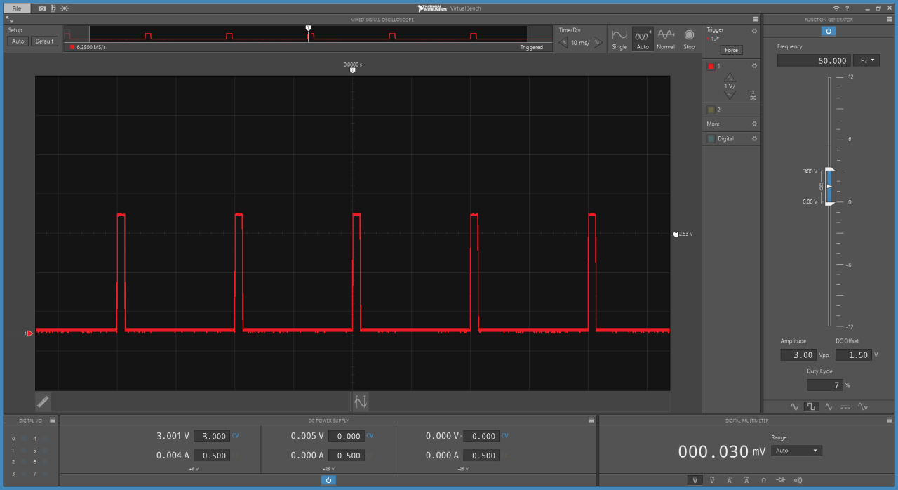
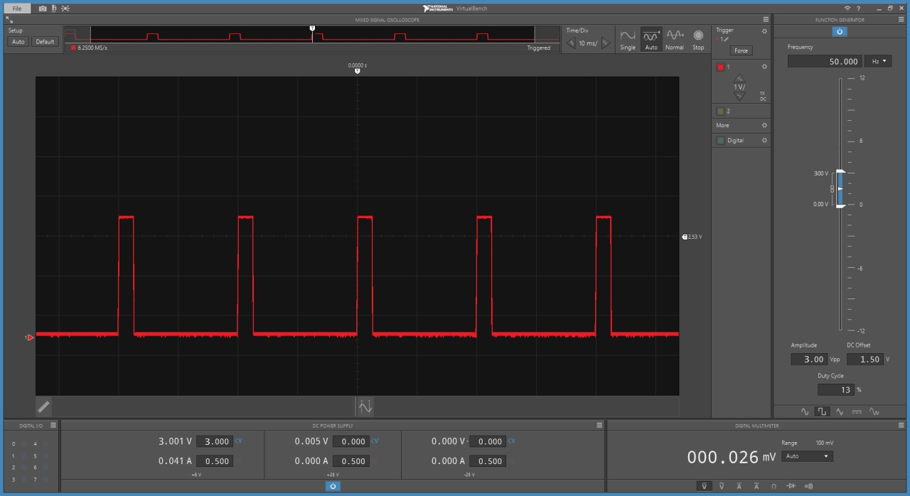
For driving the DC motor, we used PWM to quite directly switch the motor on and off. However, this is not the only use for PWM- it can also be used to transfer data, in this case by Modulating the Width of the Pulses between 1000uS and 2000uS.
Servo motors time how long the pulse is on for, and then go to an angle proportional to the length of the pulse- 0 degrees, for 1000uS, 180 degrees for 2000uS, 90 degrees for 1500uS. Wire up the servo motor as shown in the following:
The brown wire should connect to ground, the red servo wire should be connected to power (between 3 and 6 volts) and the yellow/orange wire should be connected to the function generator. Set the function generator to 50 Hz.